

Preface
Over the years, the networking landscape has undergone a significant transformation, particularly in the realm of hardware technology. Initially, networking infrastructure was characterized by a sense of mystery, with devices often likened to black boxes, their inner workings concealed from users. Leading industry players such as Cisco, Juniper Networks, and Arista Networks monopolized the market with proprietary solutions, providing connectivity but offering limited customization and transparency into their functionalities.
Moreover, these solutions often came with substantial price tags, encompassing hardware, associated software, and support services. This left consumers with little choice but to align themselves with one or more of these major vendors to ensure the smooth operation of their businesses and systems.
To support their offerings, these OEMs also established various certification tracks & programs, which have undoubtedly benefited individuals like myself in advancing our careers by providing valuable skills and knowledge for the real-world.
However, as the demand for flexibility, scalability, and cost-effectiveness grew, a new paradigm emerged: the era of whitebox switches.
Whitebox switches represent a seismic shift in networking hardware, offering a level of openness and versatility that was previously unimaginable. Unlike their opaque black box predecessors, whitebox switches are characterized by their openness and modular design. This openness empowers users to customize and optimize their network infrastructure according to their specific needs, whether it be in data centers, enterprise networks, or telecommunications environments.
The advantages of whitebox switches over black box alternatives are manifold. With whitebox switches, we can gain unprecedented control over our networking environment, allowing for fine-grained configuration and optimization. Providers such as Cumulus Networks, Pica8, and Big Switch Networks have been at the forefront of this movement, offering whitebox solutions that unlock new levels of agility and efficiency for businesses of all sizes. In this blog, I will try to explore the journey from black box switches to whitebox switches, with a specific focus on PicOS (Pica8 Operating System). PicOS is a leading network operating system designed for whitebox switches, offering a rich set of features and functionalities for modern networking environments. I will delve into simulating standard 3-tier architecture and will try to emulate the unique capabilities of PicOS and how it enables organizations to harness the power of open networking to drive innovation and growth. Additionally, we’ll examine the broader trends shaping the adoption of whitebox switches and the implications for network infrastructure in the digital age.
Installation
Pica8 offers its software in a virtual format called PicOS-V which can used to try out the various features that the OS provides.
This virtual format of the OS is compatible with various Type 1 and Type 2 hypervisors and emulators. My plan is to install PicOS-V in GNS3 and simulate a network to test various features.
PicOS-V can be downloaded from this link –
https://www.pica8.com/picos-v-download/?submissionGuid=9992ea11-358b-4c55-94ee-042c8a8ec0f9
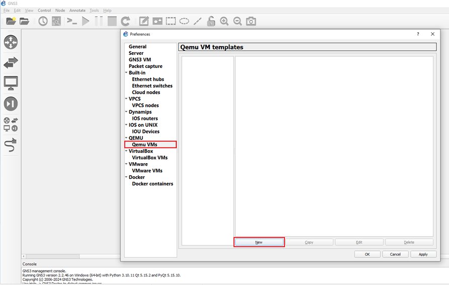
Let’s go to the GNS3 GUI and click on ‘Qemu VMs’ and then click on ‘New’. This will start the image loading wizard.
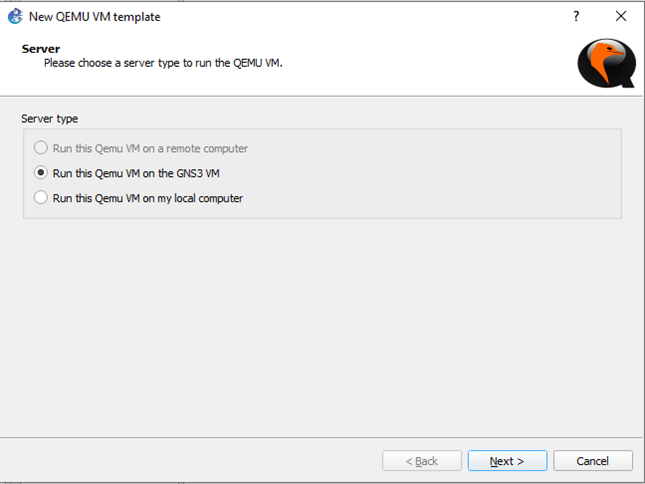
I have a GNS3 VM running in a VMWare Workstation Pro installation. So, let’s choose that.
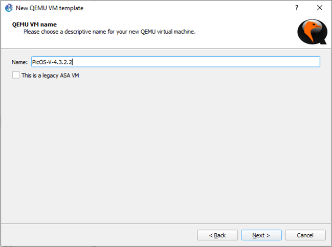
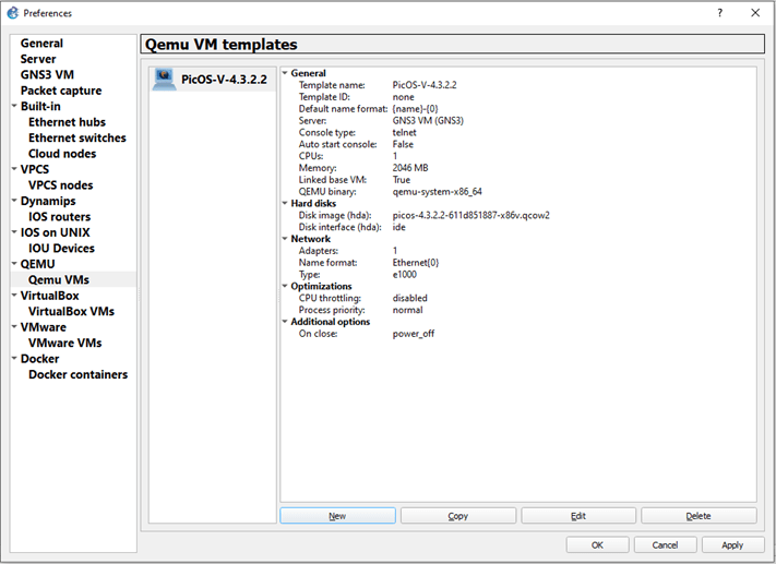
Let’s name the Qemu VM – PicOS-V-4.3.2.2 and hit ‘Next’.
Let’s select the Qemu binary as follows, change the RAM to 2GB (2048MB) and click ‘Next’.

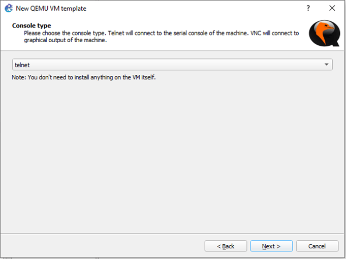
We can keep the console type as ‘Telnet’ and hit ‘Next.
Let’s click on New image and browse to the location of the OS. Once selected, the image will be start loading.
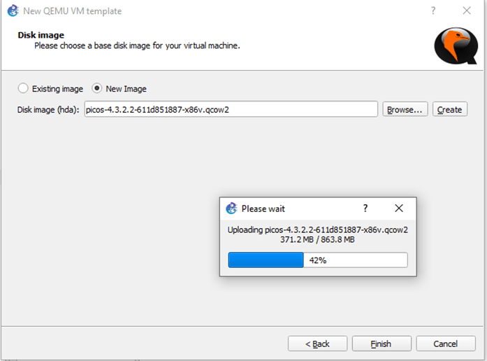
Once loading is completed, hit ‘Finish’.
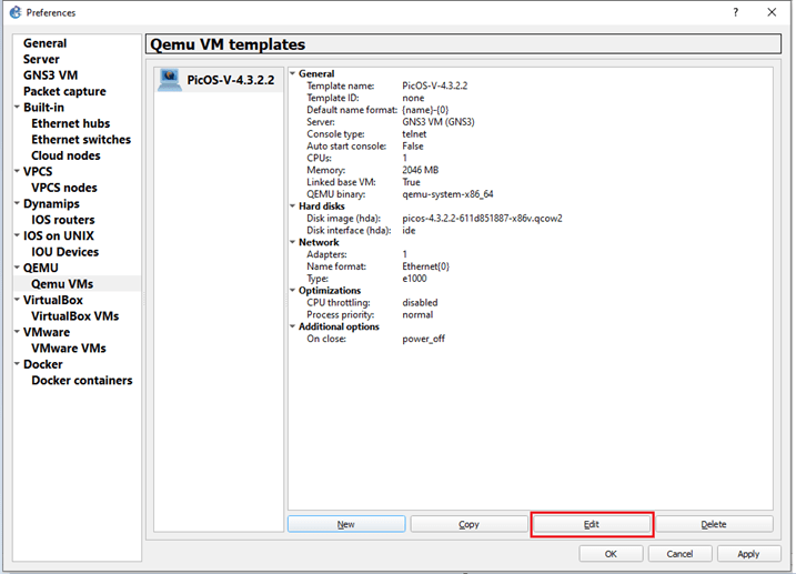
We need to adjust a few settings in this VM template before using. To do that, let’s hit ‘Edit’.
Let’s change the Symbol to ‘classis/multilayer_switch’ and Category to ‘Switches’.

Let’s click on HDD and make sure its set to ‘SATA’ for the VM.

Click on Network and set the following values
- – Adapters to ‘5’
- – Port name to ‘eth0’
- – Name format to ‘swp{port1}’
- – Type to ‘Paravirtualized Network I/O (virtio-net-pci)’
Once these are set, click ‘OK’.
eth0 is used as Out-Of-Band (OOB) management port, and nine more switch ports are added for our lab.

Initial Boot-up
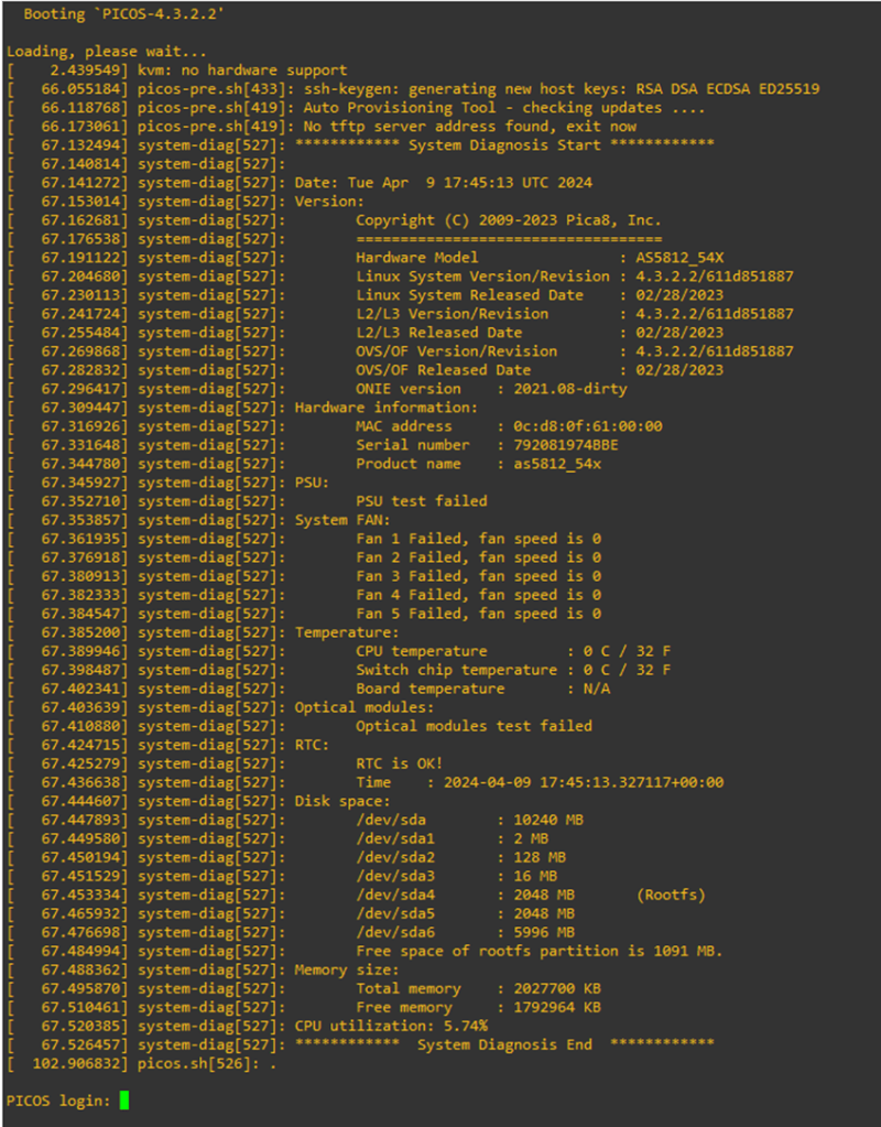
Let’s fire up our first switch to see how it looks.
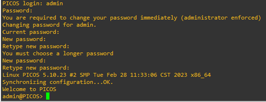
The default credential is as follows –
Username – admin
Password – pica8
The system will have you change the password after 1st login. Let’s set a secure password.
Let’s look at the management interface – eth0
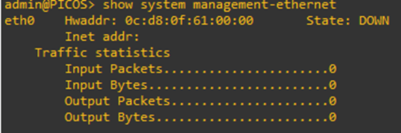
It looks like it didn’t get an IP Address. This is because this virtual switch is running within my GNS3 instance. Hence, its completely air-gapped. So, let’s fix that.
The best way to fix this is through a cloud instance. I will use the cloud instance to bridge to my host NIC.
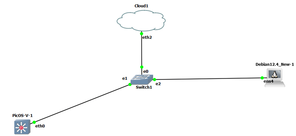
Let’s check if the switch is able to get an IP Address through DHCP or not.

I have also added a Debian-based jumpbox to test SSH and other remote features. Let’s check if the jumpbox is getting a DHCP address from my LAN network or not.
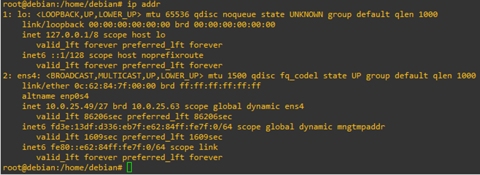
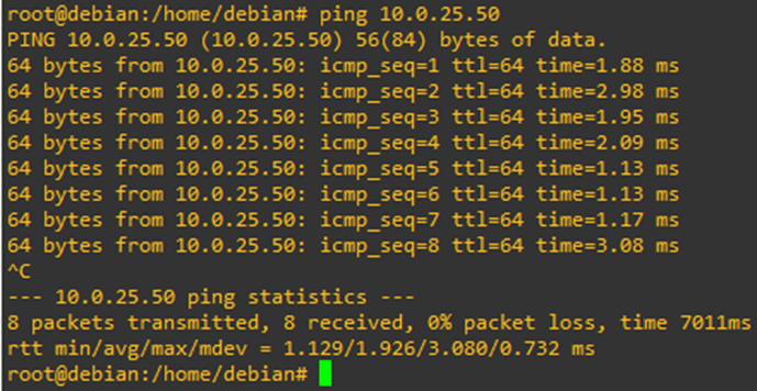
And it is! So far so good. Sure enough, I am able to ping the PicOS-V switch from the jumpbox.
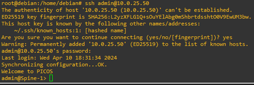
Let’s try to SSH to the switch. And I can!
Base Configuration
Available Prompts
PicOS have three prompts –
- Global mode – This is the default mode that we will land to, when we SSH to the switch. This is view-only mode of the switch.

Configure mode – This is the mode through which we will configure the various switch parameters& configurations.

Linux Shell – This is the underlying Linux shell on which PicOS is running.

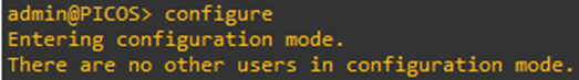
Configuration Mode
To enter configuration mode, type
Configure
Configuration Display
Let’s check the base, startup configuration of our PicOS-V switch. To check this, run the command
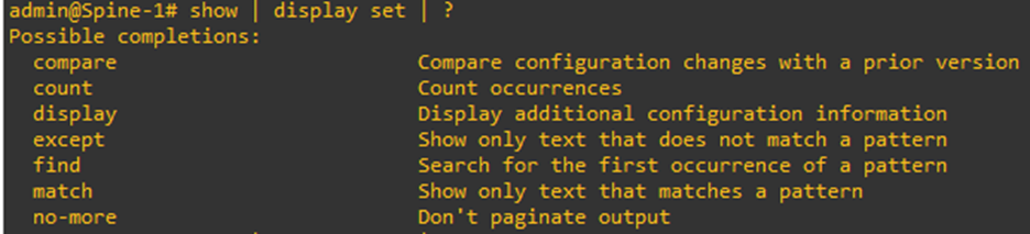
Show | display set
Show in PicOS is like show startup-config in Cisco. It displays the set configuration in the switch.
The keyword ‘display set’ after the pipe is like section or include in Cisco. The best part about PicOS is that you can you can go even a layer deeper than that.
For e.g., if you want to specifically see the set hostname in a switch, you can execute the command
Show | display set | match hostname
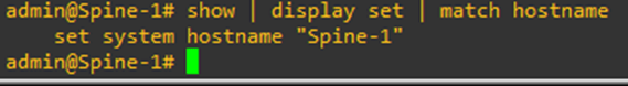
Likewise, we can choose other available options as well.
You will start with an empty slate for PicOS-V. Meaning, there will not be any base, default configuration in the switch’s startup-config.

Setting Hostname
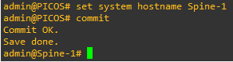
Let’s set a hostname to the switch to kick things off.
Command – set system hostname <hostname>
Once set, type commit to commit the changes. Commit in PicOS-V is comparable to ‘write memory’ in Cisco but a little bit more powerful. Anything that you will set as a part of the configuration is not going to take effect, unless the changes are committed.
Hence, powerful!
Getting into the Linux Shell of the switch
All whitebox switches out there in the market as based off some flavor of Linux. With that, they offer users to get into the Linux shell as well. PicOS is a Debian-based OS and has its own shell as well.
To get into the shell, we need to execute the command
Start shell sh
We can go to the switch’s shell from ‘view’ mode as well as ‘config’ mode. For us to go to shell from config mode, use run as a prefix.

This like the ‘do’ in Cisco world.
Saving Configuration
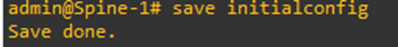
Configurations can be saved by executing the command
save <filename>
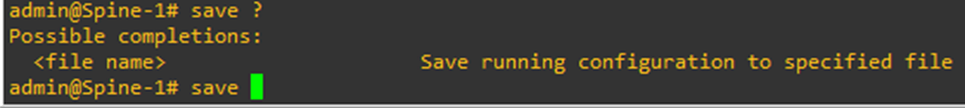
Let’s save our configurations that we have set so far.
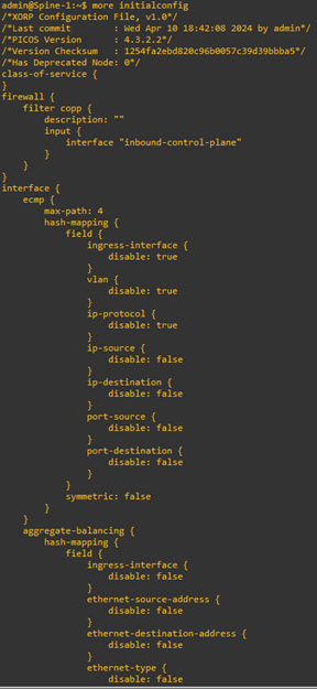
You can look into this configuration file by going into the Linux shell and executing this command
more <filename>
Below is a snippet of the file. It is a very long file which include all the default values and configuration as well.
Wiping switch Configuration
To wipe the whole switch clean of all the configurations, we need to go the directory where all configs are stores in Linux shell.
cd /pica/config/

And execute the command
sudo rm pica*
This will remove all the files that starts with pica.
Once that’s done, we need to reload the switch for it to take effect which can be executed through the command
From the ‘configure’ mode
run request system reboot
From ‘view’ mode
Request system reboot
Licensing
We can check license status of the switch by executing the command inside Linux shell
license -s
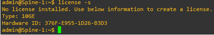
The hardware ID is important to procure/allot a license. It is like the serial# of a switch in Cisco world.
Since this is PicOS-V for evaluation, only (5) ports can be used. This also includes the management interface (eth0).
To install a license, we can run the following command
license -i

Clock & NTP configuration
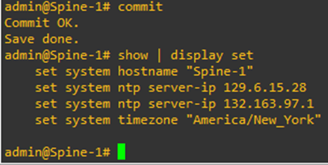
To configure NTP server, we can execute the command from the ‘configure’ mode
set system ntp server-ip
To set a source, we can execute the command
set system ntp source-interface

Let’s set some NTP servers for the switch.

Let’s set the timezone as well.


The > indicates that I have uncommitted changes to the configuration. Let’s commit them.
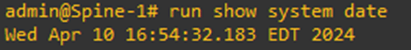
To check the current time, we can execute the command
run show system date
DNS configuration
To set system DNS server in the switch, execute the command
set system dns-server-ip <DNS server IP Address>
AAA configuration
We can set TACACS+ or RADIUS as methods of authenticating users to a switch running PicOS.
TACACS+ Configuration
To enable TACACS+, execute the command
set system aaa tacacs-plus disable false
To add a TACACS+ key, execute the command
set system aaa tacacs-plus key <tacacs-plus key>
To add TACACS+ server IP Addresses, execute the command
set system aaa tacacs-plus server-ip <Server IP Address 1>
set system aaa tacacs-plus server-ip <Server IP Address 2>
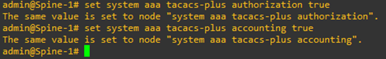
Authorization and Accounting is enabled by default on PicOS switches. So, no need to enable them.
To make the switch fallback to local credentials if TACACS+/RADIUS authentication fail, execute the command
set system aaa local-auth-fallback disable false
RADIUS Configuration
To enable RADIUS, execute the command
set system aaa radius authorization disable false
To add RADIUS server IP Addresses, execute the command
set system aaa radius authorization server-ip <Server IP Address 1>
To add a key to the configured RADIUS server, execute the command
set system aaa radius accounting server-ip <Server IP Address 1> shared-key <RADIUS key>
Local User Configuration
To add a local user, execute the command
set system login user <username> authentication plain-text-password <password>

Even though we are providing the password in plain-text, the system will encrypt it.

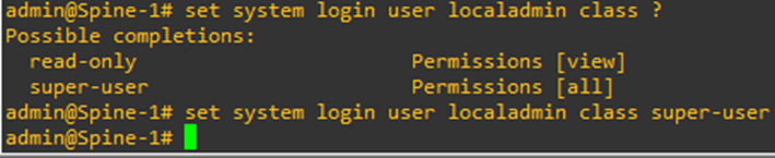
To set the role of the local user as super-user, execute the command
set system login user <username> class super-user
To set the role of the local user as read-only, execute the command
set system login user <username> class read-only
Login Announcement & Banner configuration
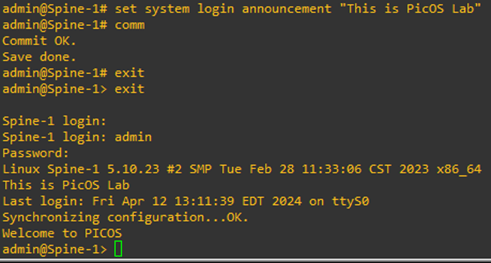
To set a login announcement, execute the command
set system login announcement “<Message>”

We should be able to see the login announcement if exit out and long back in.
To setup a muli-line banner, execute the command
set system login multiline-banner 1 message “<Message Line 1>”
set system login multiline-banner 2 message “<Message Line 2>”
set system login multiline-banner 3 message “<Message Line 3>”
set system login multiline-banner 4 message “<Message Line 4>”
Let’s set a banner for our switch.

SNMP configuration
The chronology of configuration to setup SNMPv3 is as follows –
- User creation & Group Mapping
- – SNMP ACL creation
- – MIB-View creation
- – Group-to-MIB View Mapping
- – SNMP Security configuration
Setting up SNMP User
To setup a SNMP user, issue the command
set protocols snmp v3 usm-user <SNMP user’s name> group <group name>
Setting up SNMP ACL
To configure user-based SNMP ACL, execute the command
Set system snmp-acl security-name <usm-user> network <Network with mask>
Setting up MIB-view
To set up a MIB-view, issue the command
set protocols snmp v3 mib-view <MIB-View Name> subtree 1.3.6.1 type included
This command configures an SNMPv3 MIB view named “all-access” that provides full access to all objects within the iso.org subtree of the SNMP MIB tree. It allows SNMP managers with appropriate credentials to retrieve information about all SNMP objects within this subtree when querying the PicOS device.
Group-to-MIB-view Mapping
To set up read-view, execute the command
set protocols snmp v3 group <group name> read-view <view name>
To set up write-view, execute the command
set protocols snmp v3 group <group name> write-view <view name>
To set up notify-view, execute the command
set protocols snmp v3 group <group name> notify-view <view name>
SNMP Security Configuration
To configure authentication and privacy for SNMP v3, execute the command
set protocols snmp v3 group <Group name> security-level AuthPriv
set protocols snmp v3 usm-user <usm-user> authentication-mode <authentication method or choice>
Choices are md5, none, sha.
set protocols snmp v3 usm-user <usm-user> authentication-key <key of choice>
set protocols snmp v3 usm-user <usm-user> privacy-mode <privacy method of choice>
Choices are 3des, aes128, des, none.
set protocols snmp v3 usm-user <usm-user> privacy-key <key of choice>
Let’s try to configure all this now in our switch.
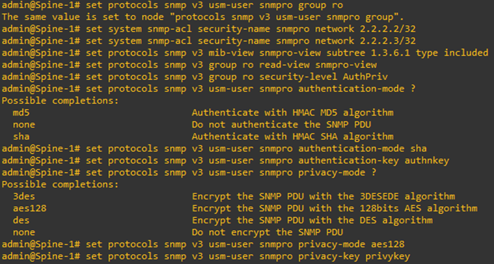
And as usual, the keys are encrypted when configuration is displayed.

SSH configuration
SSH v2 is enabled by default in PicOS switches. We can still change the other SSH-related configuration in a PicOS switch
To set connection-limit in a switch, execute the command
Set system services ssh connection-limit <No. of connections>
To setup SSH idle-timeout, execute the command
Set system services ssh idle-timeout 30
In-band Management Interface
By default, a user cannot remotely log in and manage the switch through an L3 VLAN interface, a loopback interface, a routed interface or a sub-interface. The switch, by default, is only manageable through management interface.
We need to enable the in-band management function by using the following commands to perform the SSH, TELNET, SNMP and HTTP services through the L3 interface in the default VRF.
set system inband vlan-interface <vlan-interface-name>
set system inband loopback <ip-address>
set system inband routed-interface <routed-interface-name>
Choosing loopback interface is always better as it always remains in up/up state.
Syslog Configuration
By default, the system is set to the Warning level. But to a good balance of messages, we can choose the following command
set system log-level info
By setting the logging level to “info,” you ensure that all messages with severity levels “info” and higher (“warning,” “error,” and “fatal”) are logged. This provides a balance between capturing important system events and not overwhelming the log with excessive detail.
To set a remote syslog server, execute the command
set system syslog server-ip <Server IP Address> protocol udp
Syslog protocol runs in management VRF by default. If we use Ethernet management interface Eth0/1 to connect with the syslog server, we should be good. But if an L3 VLAN interface is used to connect with the syslog server, the syslog protocol cannot run normally by default, as all the L3 VLAN interface is in the default VRF by default. To achieve this, we need to modify the configurations to make the L3 VLAN interface part of management VRF so as to run the syslog protocol normally.
To do this, execute the command
set system management-services vrf default
This command also moves the NTP/TACACS+/RADIUS management services to the default VRF.
Conclusion
This configuration serves as the foundation for any PicOS switch deployment, establishing a robust base configuration. Stay tuned for my upcoming blog posts as I explore deploying PicOS in diverse real-world scenarios to see how it handles them.

Leave a comment